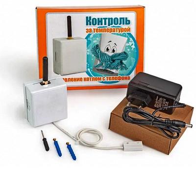
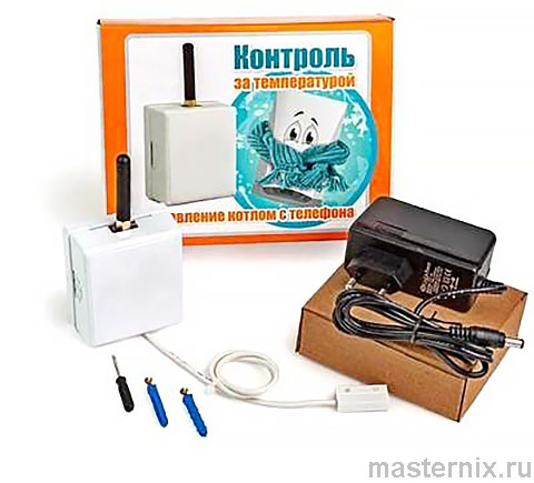
Instruction manual for configuration and operation of the GSM thermostat KotelOK
Руководство / инструкция
Быстрая настройка за 10 минут: первые шаги
Подготовка к работе: безопасность и внимательность
Прежде чем приступать к настройке Котел.ОК, настоятельно рекомендуем прочитать инструкцию до конца. Звучит банально? Возможно. Но практика показывает: 8 из 10 проблем возникают именно из-за спешки на старте.
Работаете с электроприборами — соблюдайте базовую технику безопасности. Отключайте питание при подключении проводов, не прикасайтесь к контактам под напряжением. Всё как в детстве учили, только ставки выше.
Откройте крышку устройства: нажмите сбоку на корпус в местах, отмеченных стрелками, и плавно потяните крышку на себя. Без резких движений — пластик хрупкий.
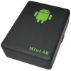
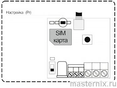
GSM модуль Котел.ОК: общий вид
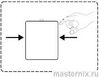
Открытие крышки прибора
На внутренней стороне крышки вы найдёте схему клеммной колодки, подсказку по запросу показаний датчиков и номер техподдержки: 8-804-333-90-80. Удобно, что всё под рукой.
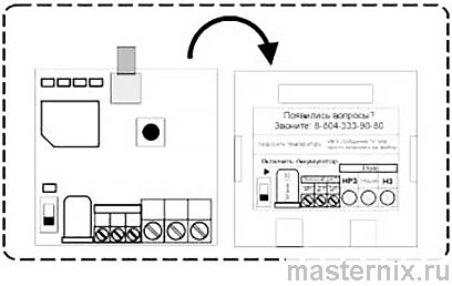
Назначение клеммной колодки
Установка SIM-карты и антенны: избегаем ошибок
Монтаж антенны и подготовка слота
Прикрутите антенну к разъёму SMA: установите её вертикально и вращайте по часовой стрелке до лёгкого сопротивления. Перетягивать не нужно — резьба пластиковая.
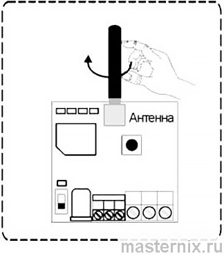
Установка антенны
Сдвиньте крышку SIM-слота вправо до щелчка. Аккуратно, без усилия — механизм фиксации нежный.
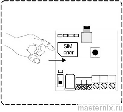
Открытие SIM-слота
Правильная установка карты и важные требования
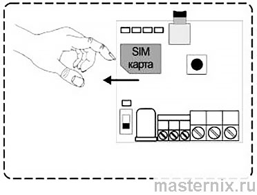
Установите SIM-карту в слот, ориентируясь по скошенному углу. Убедитесь, что контакты направлены вниз, а карта лежит ровно, без перекосов.
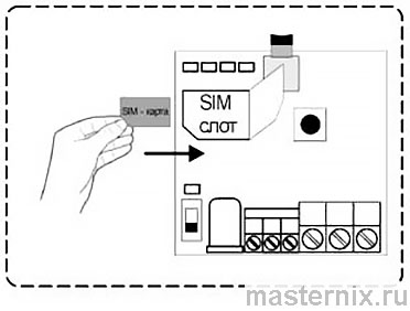
Установка SIM-карты
Закройте крышку слота и сдвиньте её влево до фиксации.
Закрытие SIM-слота
⚠️ Критически важно: отключите PIN-код на SIM-карте и удалите все сохранённые SMS. Иначе модуль не сможет корректно работать с сетью.
Подключение питания и регистрация в сети
Включение устройства и контроль индикаторов
Подключите адаптер 12В к разъёму питания и включите его в розетку 220В. Загорится зелёный индикатор 【Питание】.
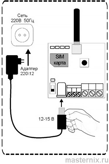
Подключение адаптера питания
Переведите переключатель 【Аккумулятор】 в положение 【ON】. Загорится индикатор резервного питания — значит, батарея подключена и готова к работе.
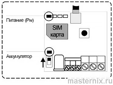
Активация аккумулятора
Подождите около 10 секунд: модуль зарегистрируется в сети GSM, и загорится индикатор 【GSM】.
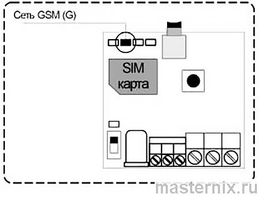
Регистрация в сети
Диагностика при проблемах с подключением
Если мигают индикаторы 【G】 и 【Pr】 — модуль не видит SIM-карту. Отключите питание, проверьте посадку карты в слоте, повторите настройку с шага установки SIM.
Если индикатор 【G】 не горит вообще:
- ✖️ Отключите питание и извлеките карту
- ✖️ Проверьте её в телефоне: активация, положительный баланс, отключённый PIN, уровень сигнала >30%
- ✖️ Верните карту в модуль и повторите процедуру с шага 3
Звучит много шагов? Зато вы исключите 95% типичных ошибок на старте.
Запись телефона для оповещений: первый звонок
Программирование номера через входящий вызов
При первом включении, если телефонная книга пуста, после регистрации в сети загорится индикатор 【Настройка】. Это сигнал: модуль ждёт вашего звонка.
Режим программирования номеров
Позвоните на номер установленной SIM-карты со своего мобильного. Модуль отклонит вызов, индикатор 【Pr】 погаснет, а вам придёт SMS: «Телефон записан. Установлены тревожные пороги температуры для Т встр. Тmin=10 Tmax=35».
Всё. Ваш номер сохранён в первой ячейке памяти. Теперь вы будете получать уведомления.
Стандартные настройки: что уже работает
Готовые пороги оповещения и реакция на события
По умолчанию модуль настроен на оповещение при выходе температуры за пределы +10…+35 °С. Это разумный диапазон для большинства помещений.
- ✔️ При превышении +35 °С вы получите SMS: «Т1=+35С»
- ✔️ При падении ниже +10 °С — аналогичное уведомление: «Т1=+10С»
- ✔️ При отключении электричества — «Основное питание отключено, работа от аккумулятора»
- ✔️ При восстановлении питания — «Питание восстановлено»
Удобно, что система реагирует не только на температуру, но и на перебои с электричеством. Особенно актуально для дач и загородных домов.
Запрос состояния устройства: команды и ответы
Два способа получить актуальные данные
Узнать текущее состояние модуля можно двумя путями:
- Позвонить на номер SIM-карты в устройстве
- Отправить SMS с командой 【S】 (латиницей)
Модуль отклонит звонок или примет SMS и в ответ пришёт детализированный отчёт:
| Параметр | Значение |
|---|---|
| Реле / Отопление | Включено / Выключено |
| Т встроенный | Значение в °С или «Откл.» |
| Т внешний | Значение в °С или «Откл.» |
| Питание | Ок / Выключено |
| Уровень GSM | Процент сигнала (0–100%) |
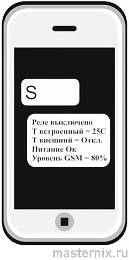
Пример №1: реле выключено, питание от сети
Что это значит на практике: реле не активно, встроенный датчик показывает 25 °С, внешний датчик не подключён, питание стабильное, сигнал сети отличный (80%).
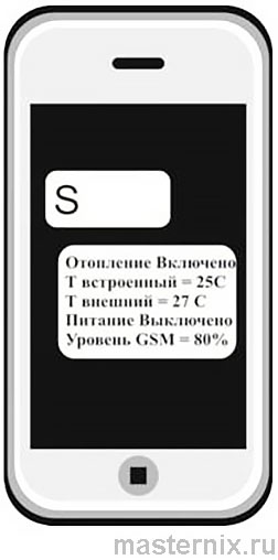
Пример №2: отопление включено, работа от АКБ
Здесь уже интереснее: отопление работает, оба датчика активны (25 °С и 27 °С), основное питание пропало — модуль перешёл на аккумулятор. Самое время проверить электросеть.
⚠️ Важный нюанс: встроенный датчик может показывать температуру с погрешностью ±1 °С, так как находится внутри корпуса. Для точных замеров используйте внешний датчик.
Настройка температурных порогов через SMS
Команда изменения границ оповещения
Чтобы изменить стандартные пороги, отправьте SMS (латиницей) в формате:
| Команда | Описание | Пример |
|---|---|---|
| 【UTn=x,y】 | n: 1=встроенный, 2=внешний| x: нижний порог| y: верхний порог | 【UT1=+5,+45】 |
После отправки команды 【UT1=+5,+45】 вы получите подтверждение: «Пороги тревожной температуры для Т встр. настроены Tmin=5 Tmax=45».
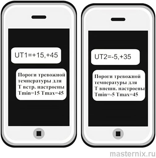
Настройка порогов: встроенный и внешний датчики
Логично? Настраиваете один раз — и система работает автономно, предупреждая только при реальных отклонениях.
Управление отоплением: поддержка заданной температуры
Принцип работы и совместимое оборудование
Модуль может управлять отопительным оборудованием, поддерживая заданную температуру. Подходит для:
- ★ Газовых котлов с электронным блоком
- ★ Электрических котлов с управлением
- ★ Электрообогревателей до 2 кВт без электроники
Принцип прост: вы задаёте целевую температуру, модуль измеряет её датчиками и включает/выключает реле при отклонениях.
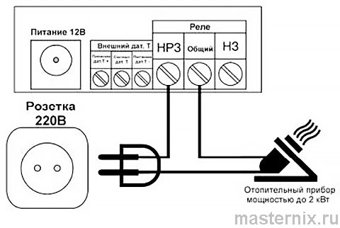
Подключение к котлу и отправка команд
Подключите модуль к клеммам внешнего термостата котла двумя проводами. Обязательно при отключённом питании!
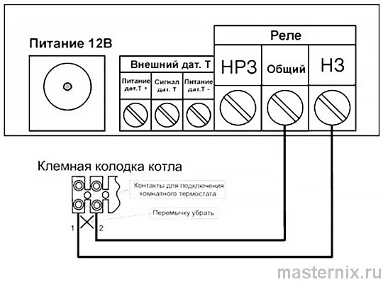
Подключение к газовому котлу
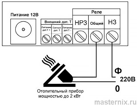
Подключение к электроприбору
Чтобы задать температуру для встроенного датчика, отправьте:
| Команда | Описание | Пример |
|---|---|---|
| 【T1=x】 | x: целевая температура от -55 до +125 °С | 【T1=+15】 |
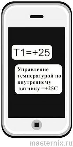
Команда для встроенного датчика
Ответ: «Управление температурой по внутреннему датчику =+15С».
Для внешнего датчика используйте команду 【T2=x】 с аналогичным синтаксисом.
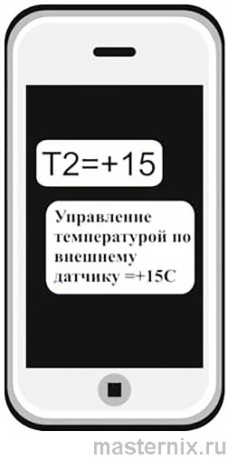
Команда для внешнего датчика
⚠️ Внимание: при активации управления по одному датчику, второй автоматически отключается. Переключайтесь осознанно.
Дистанционное включение и отключение датчиков
Чтобы отключить датчик, отправьте:
| Команда | Пример | Ответ |
|---|---|---|
| 【Px0】 | 【P10】 — отключить встроенный | «Внутренний термодатчик отключен» |
| 【Px1】 | 【P21】 — включить внешний | «Внешний термодатчик включен» |
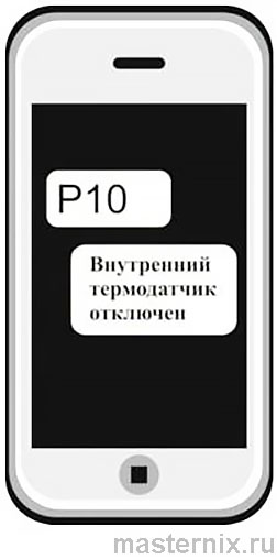
Отключение датчика
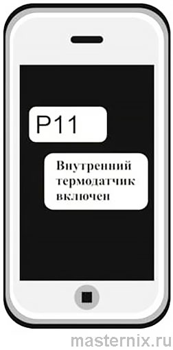
Включение датчика
Удобно, когда нужно временно исключить один из датчиков из логики управления — например, при проведении работ в помещении.
Режим дистанционного реле: включение и выключение
Использование модуля как умного выключателя
Модуль можно переключить в режим дистанционного реле — тогда он будет работать как беспроводной выключатель нагрузки до 2 кВт (10А, 220В).
Подключение в режиме реле
⚠️ Важно: в этом режиме управление температурой отключается, но оповещения о выходе за пороги продолжают работать.
Команды включения и выключения реле
| Команда | Действие | Пример |
|---|---|---|
| 【V=1】 | Включить реле | 【V=1】 |
| 【V=0】 | Выключить реле | 【V=0】 |
Ответ на включение: «Реле Включено. Управление температурой Выключено».
Ответ на выключение: «Реле Выключено. Управление температурой Выключено».
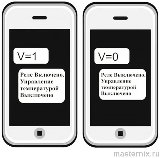
Управление реле: включить / выключить
Чтобы вернуться к температурному управлению, просто отправьте команду 【T1=...】 или 【T2=...】 с нужным значением.
Добавление номеров и управление памятью
Ручное добавление и редактирование контактов
Чтобы добавить номер через кнопку: нажмите и удерживайте 【Настройка】 2 секунды до зажигания индикатора 【Pr】, затем позвоните на модуль. После отбоя звонка придёт подтверждение с указанием позиции в памяти.
Запись номера через звонок
Для добавления через SMS используйте команду:
| Команда | Формат | Пример |
|---|---|---|
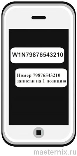
| 【WpNxxxxxxxxxxx】 | p: позиция 1–5| номер без «+» | 【W1N79201112233】 |
Ответ: «Номер 79201112233 записан на 1 позицию».
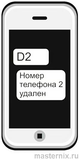
Для удаления номера отправьте:
| Команда | Пример | Ответ |
|---|---|---|
| 【Dp】 | 【D2】 — удалить позицию 2 | «Номер телефона 2 удален» |
Удаление номера из памяти
Всего доступно 5 ячеек — достаточно для семьи и доверенных лиц.
Технические характеристики и диагностика
Параметры устройства и полезные команды
Ключевые характеристики Котел.ОК:
- ☑️ Датчики: 1 встроенный + 1 внешний (DS18B20, диапазон -55…+125 °С)
- ☑️ Реле: 1 перекидной контакт, нагрузка до 10А/220В
- ☑️ Питание: адаптер 12В/1А, резервный АКБ 100 мА·ч
- ☑️ Связь: GSM 850/900/1800/1900 МГц, разъём антенны SMA
- ☑️ Рабочий диапазон: -30…+55 °С, влажность до 85%
- ☑️ Габариты: 62×67×31 мм, вес ≤100 г
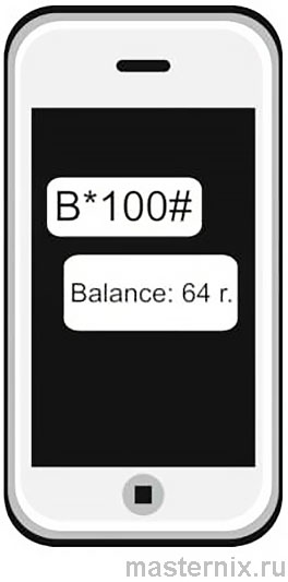
Для запроса баланса SIM отправьте: 【B*nnn#】, где nnn — USSD-код вашего оператора (например, 【B*100#】).
Запрос баланса SIM-карты
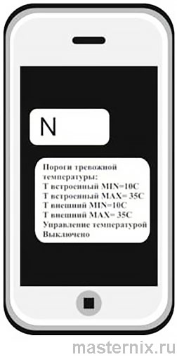
Чтобы запросить текущие настройки, отправьте команду 【N】. В ответ придёт список всех установленных порогов и режимов работы.
Запрос установленных параметров
Сброс настроек и перезагрузка
Для удалённой перезагрузки отправьте команду 【R】. Модуль перезапустится без физического доступа.
Для полного сброса к заводским настройкам: нажмите и удерживайте кнопку 【Настройка】 не менее 5 секунд. Индикатор 【Pr】 мигнёт 3 раза — память очищена, можно настраивать заново.
Остались вопросы? Техподдержка: 8-804-333-90-80 (звонок бесплатный).