IEK OP-1, OP-2e type testers for testing electrical circuits. Operating manual
Руководство / инструкция
Назначение пробников: где и как применять
Область использования и решаемые задачи
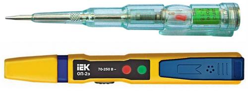
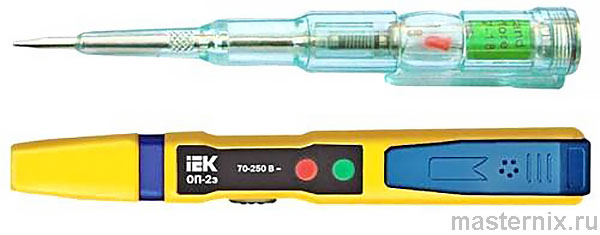
Вы наверняка держали в руках обычную отвёртку — но эта умеет «видеть» электричество. Пробники IEK ОП-1 и ОП-2э созданы для быстрой диагностики цепей переменного и постоянного тока без сложных приборов.
Где они пригодятся:
- Проверка наличия напряжения в розетках, выключателях, патронах
- Поиск обрывов проводки в автомобилях и бытовой технике
- Определение полярности аккумуляторов и гальванических элементов
- Тестирование электронных компонентов: диодов, конденсаторов, транзисторов
Практика показывает: компактный инструмент экономит время. Но есть нюанс: это не указатель напряжения по ГОСТ 20493 — для серьёзных электроустановок нужны другие средства защиты.
Рабочие условия:
- Температура: −10…+50 °C
- Высота над уровнем моря: до 2000 м
- Влажность: до 90% без конденсата
- Воздух: без пыли, дыма, коррозионных или воспламеняющих газов
Знакомо? Именно поэтому пробник работает и в гараже, и в квартире — но не под дождём и не в запылённом цехе.
Сравнение характеристик: ОП-1 против ОП-2э
Ключевые различия модификаций
| Параметр | ОП-1 | ОП-2э |
|---|---|---|
| Проверка напряжения переменного тока (контакт) | 70–250 В | 70–250 В |
| Проверка напряжения переменного тока (бесконтакт) | 70–600 В | 70–10 000 В |
| Диапазон частот | 50–500 Гц | 50–500 Гц |
| Определение полярности постоянного тока | 1,5–36 В | 1,2–36 В |
| Проверка целостности цепи (сопротивление) | 0–50 МОм | «О»: 0–5, «L»: 0–50, «Н»: 0–100 МОм |
| Индикация ВЧ-полей | ≥5 мВт/см² | «L»: ≥5, «Н»: ≥2 мВт/см² |
| Элементы питания | AG3 1,5 В × 2 | AG13 1,5 В × 2 |
| Замена батареек | 392A, LR41, 192, V3GA | LR44, 157, V13GA, A76 |
Что имеем? ОП-2э — продвинутая версия с переключателем чувствительности и расширенным диапазоном бесконтактного обнаружения. Если работаете с высоковольтными линиями — выбор очевиден.
Требования безопасности: что категорически запрещено
9 правил, которые спасут от удара током
Без сомнения, даже простой инструмент требует дисциплины. Вот список, который лучше выучить:
- Не используйте пробник с треснувшим или разобранным корпусом
- Не применяйте его как обычную отвёртку для затяжки винтов
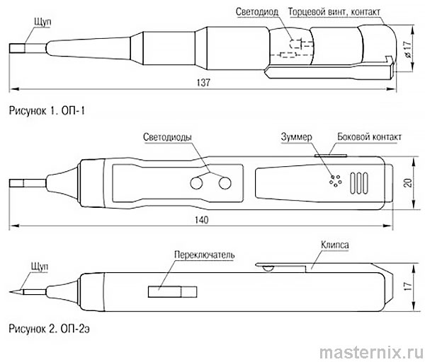
- Не прикасайтесь к торцевому винту (ОП-1) или боковому контакту (ОП-2э) при контактном методе
- Не работайте в условиях высокой влажности: дождь, роса, туман
- Не проверяйте цепи с напряжением выше указанного в характеристиках
- Не используйте пробник как указатель напряжения в электроустановках до 1000 В
- Открывайте корпус только для замены батареек
- Соблюдайте класс защиты II по ГОСТ 12.2.007.0
- Перед каждым использованием проверяйте работоспособность
Справедливости ради: большинство инцидентов происходит из-за игнорирования пункта 3. Касание контакта при проверке фазы — прямой путь к удару током. Это серьёзно.
Подготовка к работе: быстрая проверка исправности
Тест за 10 секунд перед каждым использованием
Перед стартом убедитесь, что пробник «жив»:
- Возьмите прибор за ручку
- Одной рукой коснитесь щупа, другой — торцевого винта (ОП-1) или бокового контакта (ОП-2э)
- Светодиод загорелся? Отлично, можно работать
- Нет свечения? Замените элементы питания
Важно добавить: если светодиод тусклый — батарейки на исходе. Не ждите полного отказа, поменяйте заранее. Логично?
Опыт подсказывает: 80% «неисправностей» пробника — это севшие батарейки. Проверьте этот пункт перед обращением в сервис.
Режимы работы: контактный и бесконтактный методы
Переключатель ОП-2э: три позиции для разных задач
Пробник ОП-2э имеет встроенный переключатель режимов — это его главное преимущество:
- 【О】 — контактный режим: горит красный светодиод. Для проверки напряжения при прямом касании, тестирования целостности цепей и обнаружения электромагнитных полей
- 【L】 — бесконтактный режим, низкая чувствительность: зелёный светодиод + зуммер. Для поиска напряжения в проводах без снятия изоляции
- 【Н】 — бесконтактный режим, высокая чувствительность: зелёный светодиод + зуммер. Для обнаружения слабых полей и обрывов в скрытой проводке
Пробник ОП-1 работает только в режиме, аналогичном 【О】 — без переключателя, но и без лишних сложностей.
Есть над чем подумать: высокая чувствительность 【Н】 удобна, но может реагировать на наводки. Начинайте с 【L】, повышайте только при необходимости.
Диагностика переменного тока: пошаговый алгоритм
Контактный метод: проверка при прямом касании
- Возьмите пробник за ручку, не касаясь металлического винта/контакта
- Прикоснитесь щупом к оголённому участку токоведущей части
- Свечение светодиода = наличие напряжения 70–250 В
Просто? Да. Но есть нюанс: если светодиод не горит — это не всегда «нет напряжения». Возможно, плохой контакт или севшая батарейка. Перепроверьте.
Бесконтактный метод: поиск без вскрытия изоляции
- Для ОП-2э переключитесь в режим 【L】 или 【Н】
- Поднесите щуп к изоляции провода, розетке, выключателю или корпусу прибора
- Свечение светодиода и/или звук зуммера = наличие напряжения
- Для повышения чувствительности: коснитесь пальцем торцевого винта (ОП-1) или бокового контакта (ОП-2э)
Практика показывает: этот метод идеален для поиска фазы в пучке проводов или проверки целостности скрытой проводки. Но помните: толстая изоляция или экранирование могут ослабить сигнал.
Работа с постоянным током: полярность и заряд
Определение полярности аккумулятора
Для высокой чувствительности держите пробник за ручку, касаясь пальцем торцевого винта (ОП-1) или бокового контакта (ОП-2э):
- Щупом поочерёдно коснитесь полюсов аккумулятора
- Одновременно пальцем другой руки дотроньтесь до свободного полюса
- Свечение светодиода = щуп на положительном полюсе
Что имеем? Быстрый способ не перепутать «плюс» и «минус» при подключении оборудования. Бывает и так: маркировка стёрлась — пробник спасёт.
Оценка заряда гальванического элемента
- Коснитесь щупом отрицательного полюса элемента
- Свободной рукой коснитесь положительного полюса
- Слабое свечение = элемент разряжен, отсутствие свечения = заряжен
Звучит парадоксально? Да, но это особенность схемы пробника. Не путайте с обычными тестерами — здесь логика обратная.
Проверка целостности обесточенных цепей
Прозвонка проводов и компонентов без питания
Алгоритм прост:
- Прикоснитесь щупом к одному концу цепи
- Пальцами свободной руки коснитесь другого конца
- Свечение светодиода = цепь цела, отсутствие = обрыв
Важно добавить: этот метод работает только для пассивных (обесточенных) цепей. Под напряжением — только контактный или бесконтактный метод из раздела 6.
Опыт подсказывает: для длинных проводов касайтесь зачищенных участков — окислы на концах могут дать ложный «обрыв».
Тестирование электронных компонентов: конденсаторы, диоды, транзисторы
Быстрая диагностика без мультиметра
Конденсатор:
- Соедините полюса конденсатора через пробник пальцами
- Кратковременная вспышка светодиода = исправен
- Повторите с обратной полярностью — вспышка должна повториться
Диод или выпрямитель:
- Соедините выводы диода через пробник
- Поменяйте полярность подключения
- Свечение только в одном направлении = исправен
| Подключение пробника | Индикация при исправном выпрямителе | |
|---|---|---|
| между + и − | щуп к +: есть | щуп к −: нет |
| между ~ и ~ | нет | нет |
| между + и ~ | щуп к +: есть | щуп к ~: нет |
| между − и ~ | щуп к −: нет | щуп к ~: есть |
Транзистор п-р-п:
- Светодиод засветится при касании щупом коллектора 【С】 и эмиттера 【Е】, если пальцем соединить винт/контакт с базой 【В】
Транзистор р-п-р:
- Светодиод засветится при касании щупом базы 【В】, если поочерёдно соединять винт/контакт с коллектором 【С】 и эмиттером 【Е】
Лампочка, катушка реле, предохранитель, динамик:
- Коснитесь одного полюса изделия рукой
- Щупом пробника (держа его за винт/контакт) коснитесь другого полюса
- Яркое свечение = исправно, слабое или отсутствие = неисправно
Есть над чем подумать: этот метод даёт ориентировочную оценку. Для точных измерений всё же нужен мультиметр.
Поиск неисправностей: обрывы, заземление, выключатели
Поиск обрыва в проводе под напряжением
- Возьмите ОП-2э за щуп, переключите в режим 【Н】
- Проведите пробником вдоль провода от точки подключения к сети
- В месте обрыва светодиод погаснет, зуммер замолчит
Практика показывает: метод работает для проводов в изоляции, но не для экранированных кабелей. Для последних нужен специнструмент.
Проверка положения однополюсного выключателя
- Вставьте вилку прибора в розетку, выключатель — в положение «выкл»
- Поднесите щуп к рабочему элементу (цоколь лампы, ТЭН и т.п.)
- Свечение = выключатель в нулевом проводе (неправильно)
- Поменяйте полюса вилки, убедитесь в отсутствии свечения
Важно добавить: правильное подключение — выключатель в фазном проводе. Это требование ПУЭ, а не рекомендация.
Проверка заземления корпусов бытовой техники
- Прикоснитесь щупом к корпусу включённого прибора
- Свечение светодиода = заземление отсутствует (опасно!)
- Отсутствие свечения = корпус заземлён правильно
Это серьёзный аргумент в пользу регулярной проверки: отсутствие заземления — риск поражения током при пробое изоляции.
Замена батареек и условия хранения
Пошаговая замена элементов питания
Для ОП-1:
- Открутите торцевой винт против часовой стрелки
- Снимите пружину и металлическую заглушку
- Отогните проволочку, удерживающую батарейки
- Установите новые батарейки отрицательным полюсом внутрь
- Соберите в обратном порядке
Для ОП-2э:
- Аккуратно оттяните клипсу вверх, сдвиньте её с корпуса
- Установите батарейки согласно маркировке полярности
- Верните клипсу на место до щелчка
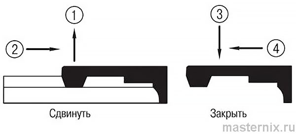 Рисунок 3.
Важно добавить: используйте только указанные типы батареек. Неподходящий размер или напряжение могут повредить схему.
Условия хранения и гарантийные обязательства
Хранение:
- В упаковке изготовителя, в помещении с естественной вентиляцией
- Температура: −45…+50 °C, влажность 60–80%
- Без прямого попадания влаги и механических воздействий
Транспортировка:
- Любым видом крытого транспорта
- С защитой от повреждений, загрязнения и влаги
Гарантия:
- Срок эксплуатации: 1 год с даты продажи
- Распространяется при соблюдении правил эксплуатации и хранения
- На элементы питания гарантия не действует
Опыт подсказывает: 90% обращений по гарантии — это не брак, а нарушение условий использования. Проверьте раздел «Требования безопасности» перед претензией.
«ИЭК РОССИЯ»
117545, Москва, 1-й Дорожный проезд, д. 4, строение 1
Тел.: 788-8845, 788-8846 Факс: 788-8847 www.iek.ru